
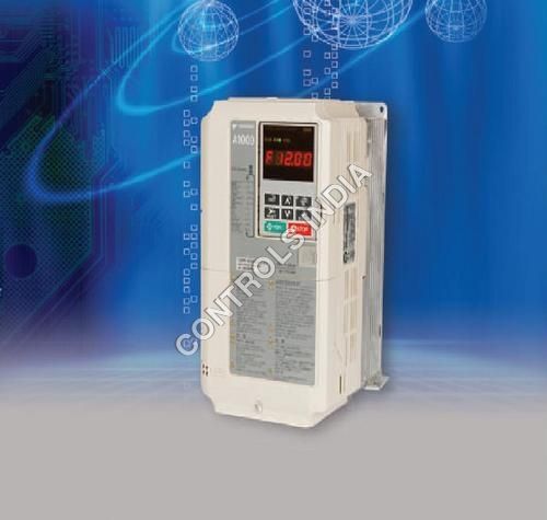
Product Description
Specification
| Standard Specifications | Model CIMR-AD4A | 0002 | 0004 | 0005 | 0007 | 0011 | 0018 | 0023 | 0031 | 0038 | 0044 | 0058 | 0072 | 0088 | 0103 | 0139 | 0165 | 0208 | 0250 | 0296 | 0362 | 0414 | 0515 | 0675 | ||||||
| Typical Motor Capacity | Normal Duty | 0.75 | 1.5 | 2.2 | 3 | 5.5 | 7.5 | 11 | 15 | 18.5 | 22 | 30 | 37 | 45 | 55 | 75 | 90 | 110 | 132 | 160 | 185 | 220 | 250 | 355 | ||||||
| Heavy Duty | 0.4 | 0.75 | 1.5 | 2.2 | 3.7 | 5.5 | 7.5 | 11 | 15 | 18.5 | 22 | 30 | 37 | 45 | 55 | 75 | 90 | 110 | 132 | 160 | 185 | 220 | 315 | |||||||
| Rated Output Capacity in KVA | Normal Duty | 1.6 | 3.1 | 4.1 | 5.3 | 8.5 | 13.3 | 17.5 | 24 | 29 | 34 | 44 | 55 | 67 | 78 | 106 | 126 | 159 | 191 | 226 | 276 | 316 | 392 | 514 | ||||||
| Heavy Duty | 1.4 | 2.6 | 3.7 | 4.2 | 7 | 11.3 | 13.7 | 18.3 | 24 | 30 | 34 | 46 | 57 | 69 | 85 | 114 | 137 | 165 | 198 | 232 | 282 | 343 | 461 | |||||||
| Rated Output Current A | Normal Duty | 2.1 | 4.1 | 5.4 | 6.9 | 11.1 | 17.5 | 23 | 31 | 38 | 44 | 58 | 72 | 88 | 103 | 139 | 165 | 208 | 250 | 296 | 362 | 414 | 515 | 675 | ||||||
| Heavy Duty | 1.8 | 3.4 | 4.8 | 5.5 | 9.2 | 14.8 | 18 | 24 | 31 | 39 | 45 | 60 | 75 | 91 | 112 | 150 | 180 | 216 | 260 | 304 | 370 | 450 | 605 | |||||||
| Enclosure Type | NEMA-1(can be used as IP00 by removing top & bottom covers) | IP00 | | |||||||||||||||||||||||||||
| Overload Tolerance | Normal Duty Rating: 120% of rated output current for 60 s | Heavy Duty Rating: 150% of rated output current for 60s | | |||||||||||||||||||||||||||
| Max. Output Voltage | Proportional to input voltage | | ||||||||||||||||||||||||||||
| Max. Output Frequency | 400 Hz | | ||||||||||||||||||||||||||||
| Rated Voltage / Rated Frequency | Three-phase 380 to 480 VAC, 50/60 Hz, | | ||||||||||||||||||||||||||||
| Allowable Voltage Fluctuation | -15% to +10% | | ||||||||||||||||||||||||||||
| Allowable Frequency Fluctuation | -/+ 5% | | ||||||||||||||||||||||||||||
| Harmonic Suppression | DC Reactor | Option | Built-in | | ||||||||||||||||||||||||||
| Braking | Function | Braking Chopper | Built-in | Option | | |||||||||||||||||||||||||
| | Control Method | V/f Control, V/f Control with PG, Open Loop Vector Control, Closed Loop Vector Control with PG, Open Loop Vector Control for PM, | | |||||||||||||||||||||||||||
| | | Advanced Open Loop Vector Control for PM, Closed Loop Vector Control for PM | | |||||||||||||||||||||||||||
| Frequency Control Range | 0.01 to 400 Hz | | ||||||||||||||||||||||||||||
| Frequency Setting Resolution | Digital reference: 0.01 Hz | | ||||||||||||||||||||||||||||
| | | Analog reference: 0.03 Hz / 60 Hz (11 bit) | | |||||||||||||||||||||||||||
| Output Frequency Resolution | 0.001 Hz | | ||||||||||||||||||||||||||||
| Frequency Setting Signal | -10 to +10 V, 0 to +10 V, 4 to 20 mA, pulse train | | ||||||||||||||||||||||||||||
| Starting Torque | 150%/3 Hz (V/f Control and V/f Control with PG), 200%/ 0.3 Hz (Open Loop Vector Control), 200%/0 RPM (Closed Loop Vector Control, Closed Loop | | ||||||||||||||||||||||||||||
| istics | | Vector Control for PM, and Advanced Open Loop Vector Control for PM), 100%/5% speed (Open Loop Vector Control for PM) | | |||||||||||||||||||||||||||
| Speed Control Range | 1:1500 (Closed Loop Vector Control and Closed Loop Vector Control for PM) | | ||||||||||||||||||||||||||||
| | | 1:200 (Open Loop Vector Control) 1:40 (V/f Control and V/f Control with PG) | | |||||||||||||||||||||||||||
| l Character | | 1:20 (Open Loop Vector Control for PM) 1:100 (Advanced Open Loop Vector Control for PM) | | |||||||||||||||||||||||||||
| Speed Control Accuracy | -/+ 0.2% in Open Loop Vector Control (25 degree C -/+ 10 degree C) , -/+ 0.02% in Closed Loop Vector Control (25 degree C -/+ 10 degree C) | | ||||||||||||||||||||||||||||
| Speed Response | 10 Hz in Open Loop Vector Control (25 degree C -/+ 10 degree C), 50 Hz in Closed Loop Vector Control (25 degree C -/+ 10 degree C) (excludes temperature fluctuation when performing | | ||||||||||||||||||||||||||||
| Contro | | Rotational Auto Tuning) | | |||||||||||||||||||||||||||
| Accel/Decel Time | 0.00 to 6000.0 s (4 selectable combinations of independent acceleration and deceleration settings) | | ||||||||||||||||||||||||||||
| Braking Torque | Drives of 200/400V 30kW (ND) or less have a built-in braking transistor | | ||||||||||||||||||||||||||||
| | | (Over excitation Deceleration, High Slip Braking: approx. 40%) | | |||||||||||||||||||||||||||
| | | Continuous regen. torque: approx. 20% (approx. 125% with dynamic braking resistor option: 10% ED,10 s, internal braking transistor) | | |||||||||||||||||||||||||||
| V/f Characteristics | User-selected programs and V/f preset patterns possible | | ||||||||||||||||||||||||||||
| Main Control Functions | Torque Control, Droop Control, Speed/Torque Control switch, Feed Forward Control, Zero Servo Control, Momentary, Power Loss Ride-Thru, Speed Search, Over torque | | ||||||||||||||||||||||||||||
| | | detection, torque limit, 17 Step Speed (max.), accel/decel, time switch, S-curve accel/decel, 3-wire sequence, Auto-Tuning (rotational, stationary), Online Tuning, Dwell | | |||||||||||||||||||||||||||
| | | control. | | |||||||||||||||||||||||||||
| Protection Function | Motor Protection | Motor overheat protection based on output current | | |||||||||||||||||||||||||||
| Overvoltage Protection | 200 V class: Stops when DC bus exceeds approx. 410 V, 400 V class: Stops when DC bus exceeds approx. 820 V | | ||||||||||||||||||||||||||||
| Undervoltage Protection | 200 V class: Stops when DC bus exceeds approx. 190 V, 400 V class: Stops when DC bus exceeds approx. 380 V | | ||||||||||||||||||||||||||||
| Momentary Power Loss Ride-Thru | Stops immediately after 15 ms or longer power loss (default). Continuous operation during power up to 2 s (standard). | | ||||||||||||||||||||||||||||
| Stall Prevention | Stall prevention during acceleration/deceleration and constant speed operation | | ||||||||||||||||||||||||||||
| Ground Fault Protection | Protection by electronic circuit | | ||||||||||||||||||||||||||||
| Interface | Charge LED | Charge LED remains lit until DC bus has fallen below approx. 50 V | | |||||||||||||||||||||||||||
| Digital Inputs | 8 nos. programmable (24 VDC Sink/Source/ External supply configurable) | | ||||||||||||||||||||||||||||
| Digital Outputs | 4 nos. (1 fixed / 3 programmable) 2 nos. open collector - | 48 VDC & 2 nos. Relay - 230VAC / 30 VDC | | |||||||||||||||||||||||||||
| Analog Inputs | 3 nos. Programmable - 2 nos. 0 to -/+ 10 VDC & 1 no. 0/4 to 20mA | | ||||||||||||||||||||||||||||
| Analog Outputs | 2 nos. Programmable -10 to +10 VDC | | ||||||||||||||||||||||||||||
| Pulse Train I/O | 0 to 32 kHz max. - 1 no. input & 1 no. output | | ||||||||||||||||||||||||||||
| Communication | Modbus RS422 / RS485 with speed upto 115.2 kbps | | ||||||||||||||||||||||||||||
| Safety I/O | 2 nos. hardware base block inputs & 1 no. Safety Electronic Device Monitor Output (Complying to UL508C, EN954-1 Cat.3, IEC/EN61508 SIL2) | | ||||||||||||||||||||||||||||
| Option | I/O | Analog Input (AI-A3) - 3 AI, Digital Input (DI-A3) - 16 DI, Analog Monitor (AO-A3) - 2 AO, Digital Output (DO-A3) - 8 DO | | |||||||||||||||||||||||||||
| Encoder Interface | PG-B3 for Complimentary Type PG upto 50KHz, PG-X3 for Line Driver Type PG upto 300KHz | | ||||||||||||||||||||||||||||
| Communication | PROFIBUS-DP (SI-P3), Device Net (SI-N3), CAN open (SI-S3), MECHATROLINK-2 (SI-T3) | | ||||||||||||||||||||||||||||
| Others | LCD Operator, External 24V supply; Braking unit | | ||||||||||||||||||||||||||||
| Environment | Area of Use | Indoors | | |||||||||||||||||||||||||||
| Ambient Temperature | -10 to +50 degree C | | ||||||||||||||||||||||||||||
| Humidity | 95% RH or less (no condensation) | | ||||||||||||||||||||||||||||
| Storage Temperature | -20 to +60 degree C (short-term temperature during transportation) | | ||||||||||||||||||||||||||||
| Altitude | Up to 1000 meters | | ||||||||||||||||||||||||||||
| Shock | 2 2 210 Hz to 20 Hz, 9.8 m/s max. 20 Hz to 55 Hz, 5.9 m/s (400 V: 55 kW - HD or more) or 2.0 m/s max. (400 V: 75 kW- HD or less) | | ||||||||||||||||||||||||||||
| | Standard Compliance | RoHS compliant | UL 508C, EN61800-3, EN61800-5-1, EN954-1 Cat.3, ISO 13849-1 (Cat.3, PLd), IEC/EN61508 SIL2 | | ||||||||||||||||||||||||||
GST : 24AAFCC6538D1ZW
- Nandkutir, 3rd Floor, Near Doctor House, Ellisbridge,Ahmedabad - 380006, Gujarat, India
- Phone :View Number
- Mr. Parag Parikh (Director)
- Mobile :View Number
-
 Send Inquiry
Developed and Managed by Infocom Network Private Limited.

